 Material Add Flat Plate Layout ( Modeling )
Tool summary :
Also see :
- Plates (topic)
- Miscellaneous members versus legacy miscellaneous members (topic)
- Plate layout miscellaneous member (instead of legacy)
- Multi-sided Flat Plate Material (opens when you add a flat plate layout material or legacy misc member)
- Use this point as new base position (useful DXDY option)
- Unrolled surface template (may be created in the submaterial detail for a flat play layout that is bent)
- Add Material
- Show legacy miscellaneous members in member add screen (for adding a legacy misc mem using F2 )
page 1 | contents | add material | add legacy misc mem | multi-sided flat plate window | top
Adding a flat plate layout material or legacy miscellaneous member :
Multi-sided flat plate may be laid out in a plan view or an elevation view . These instructions assume that you are using a 3-button mouse.
1 . Multi-sided flat plate work points should be done in a view whose work plane is orthogonal to (at right angles to) the material or legacy miscellaneous member being added. Do one (1) of the following:
To add a multi-sided flat plate TO a member (pre-selection method):
- Select the one (1) member that you want to add the material to (so that it is displayed in the " Primary selection color ") > press F3 > filter for "
Plate / Bar " > double-click " Flat Plate Layout " > continue to step 2.
- Instead of using F3, you can activate the Add Flat Plate Layout tool by clicking the icon represented at the top of this page or by using a keyboard shortcut or by using the classic menu system or etc.
To add a multi-sided flat plate AS a legacy miscellaneous member: Confirm that the box is checked for User and Site Options > Site > "
Miscellaneous steel " > double-click " Miscellaneous -- Flat Plate Layout" > continue to step 2.
Also see: Plate layout miscellaneous member
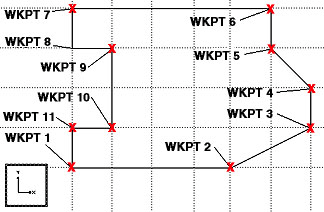
2 . The status line prompts, " Add: Material ." Locate - Complete - Return mouse bindings become active. Select the appropriate Locate option, then place work points as described below. The following illustration shows work points for a multi-sided flat plate laid out in a plan view.
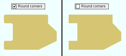
2a : Corner rounding options appear on either a window (classic) or on a section of the ribbon's Layout page (lighting). As you left-click ( Locate ) to define points, remember to set corner rounding for the most recently located point before you left-click ( Locate ) to define the next point. Below is an example of a multi-sided flat plate with and without corner rounding.
2b (optional) : If you accidentally left-click ( Locate ) at a point you do not want, hold down Shift and left-click ( Remove ) to remove that point. You can remove as many points as you like, then continue locating points as described in 2a.
2c : Middle-click ( Complete ) with your mouse pointer anywhere in the view. This locates the final point exactly where you placed the starting point.
2d : Define a material reference point . This reference point is used to dimension the material during automatic detailing of members. For a legacy miscellaneous member such as that shown below, the reference point is dimensioned on the member detail only if you locate that reference point somewhere other than a corner of the material.
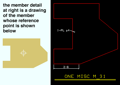
|
| The reference point in this example is dimensioned on the member detail . |
3 . After you have located the material reference point, the Multi-Sided Flat Plate Material window opens.
1a : " Material thickness " and " Steel grade " and " Thickness reference point " and " Surface finish " and " Color " and " Checkered " are filled out with default settings that match the last multi-sided flat plate that you added or edited in your current Modeling session. If you did not previously add or edit such a plate, default settings populate the window. You should change these settings as you see fit, then press the " OK " button.
Tip: The near side of the multi-sided flat plate is the face of the plate you were looking at in the view in which you added the plate (unless you rotated around the Y or Z axes). You can use the " Thickness reference point " option to set whether the thickness of the plate is on the near side, far side or center of the plate.
4 . The Rotate Material window opens, and a preview of the new multi-sided flat plate is shown on screen. Do one (1) of the following:
Alternative 1 : Press " Cancel " to back up to step 2. This stops the multi-sided plate from being added.
Alternative 2 : To accept the material's present rotation, press the " OK " button. Go to step 5 if you are adding a material.
Alternative 3 : Change the material's rotational settings and then press " OK " if you want to rotate the material.
5 : Different end steps are required depending on whether you are adding a material to a member or adding a stand-alone legacy miscellaneous member.
End steps for adding a material TO a member: After rotating the material into place > right-click ( Return ) if done adding material to the member > Change All Options can be applied if the member the material is being added to is batched together with other members with the same mark.
End steps for adding a material AS a legacy miscellaneous member: After rotating the legacy miscellaneous member into place > right-click ( Return ) when you are done.
Tip 1: If you added a legacy miscellaneous member (see step 1), you cannot re-open the Multi-Sided Flat Plate window using Edit Member -- that opens the [Legacy] Miscellaneous Member Edit window. Multi-Sided Flat Plate is a material window, not a member window, and you therefore have to open it by, for example, using Edit One Material , " Edit Other " on the context menu, or by double-clicking the material in the Model Tree .
Tip 2: If you added this material as a submaterial (see step 1), you can, in addition to the edit methods described in tip 1, double-click the material to re-open the Multi-Sided Flat Plate window.
page 1 | contents | add material | add legacy misc mem | multi-sided flat plate window | top